If you've even been in a bar sometime in the early 2000s, odds are that you likely spotted a Golden Tee arcade cabinet in the corner. If you're lucky, you've played it before: you recall the satisfying feeling smacking a trackball as hard as you can, admiring the crude graphics in a series of pseudo-realistic exotic courses with a dynamic gameplay, and a pair of professional commentators. It's a great bar game, and the nature of the trackball made it so unique and different from any other golf videogame you could play.
Preamble
When I was younger, my parents attended an arcade auction and picked up an old version of Golden Tee Fore for our basement. The cabinet itself was in bad shape, enduring likely more than a decade of wear in the corner of a no-name bar. The hardware was aging, its power supply often failing to provide the game board the proper voltage, while the CRT monitor often lost shades of color throughout gameplay. The version we had only included five courses, but the game provided endless hours of fun amongst family and friends.
Fast forward to 2021: I spot a Golden Tee Fore 2005 cabinet online, it's a few hours away and can be had for couple hundred dollars. I inquire about the condition and start to confirm logistics: how will I get a 330lb. arcade cabinet back home and safely into my basement? I tried to procure transport; understandably the buyer was not interested in working with a shipping company, despite my generous offer. Relegated, I pondered: could you build a Golden Tee cabinet?
There was two things I needed to validate:
- Could I accurately re-create a Golden Tee cabinet using my limited workworking knowledge?
- Could I procure the necessary technical components and parts necessary to play the game?
Hint: yes. Let's talk about the first part here.
Design
Turns out that building and designing arcade cabinets is a bit of a niche hobby, and I was able to find a number of resources that provided direction on the matter. I knew I didn't have any of the equipment to build the a cabinet manually, but I do have some experience using CAD and CNC mills.
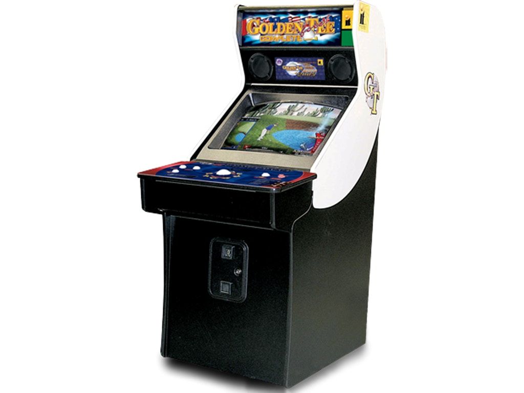
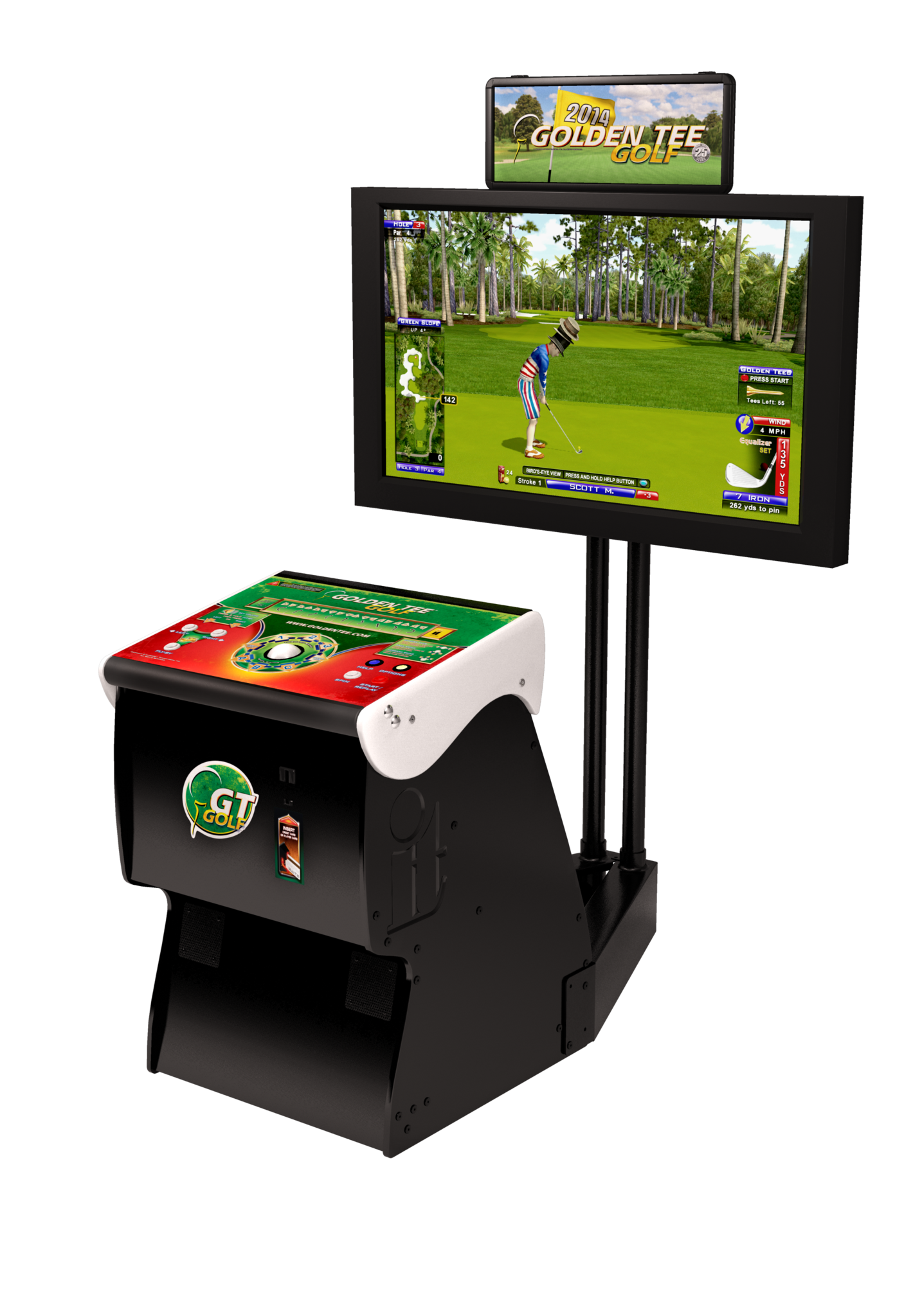
It also turned out that these days, Golden Tee isn't sold as a full cabinet, but rather a "showpiece" that has the monitor physically detached and mounted separately. This meant to me the build difficulty was decreased somewhat materially as I could simply mount a TV and only have to build the standing cabinet.
I took inspiration from a number of patrons of ArcadeControls.com, mostly notably this thread from more than a decade ago, tracking a build from start to finish. In this case, the user, jikkjack, relied on purchasing the "Golden Tee Live - Home Edition", so he would have original hardware, including the control board, but without the cabinet itself. I'm not sure if this product combination exists any further as Incredible Technologies sells the "home edition" for just shy of $4k. Oof.
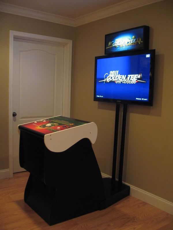
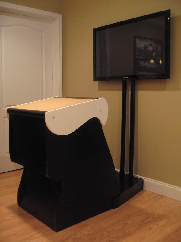
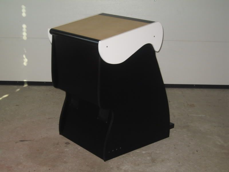
Jikkjack's build from 2010 documented on the ArcadeControls forum.
Further down in the thread, Jikkjack uploaded a Visio file with a rough plan for the unit. Since 2011, it's been downloaded more than 1500 times, so it seems I'm not the only one eager to build my own cabinet:
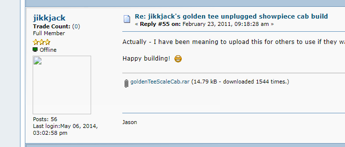
The downside is that the file provided was both a Visio file, which is not quite the preferred format for CNC machines, nor was it exceptionally detailed about the specifics of a cabinet.
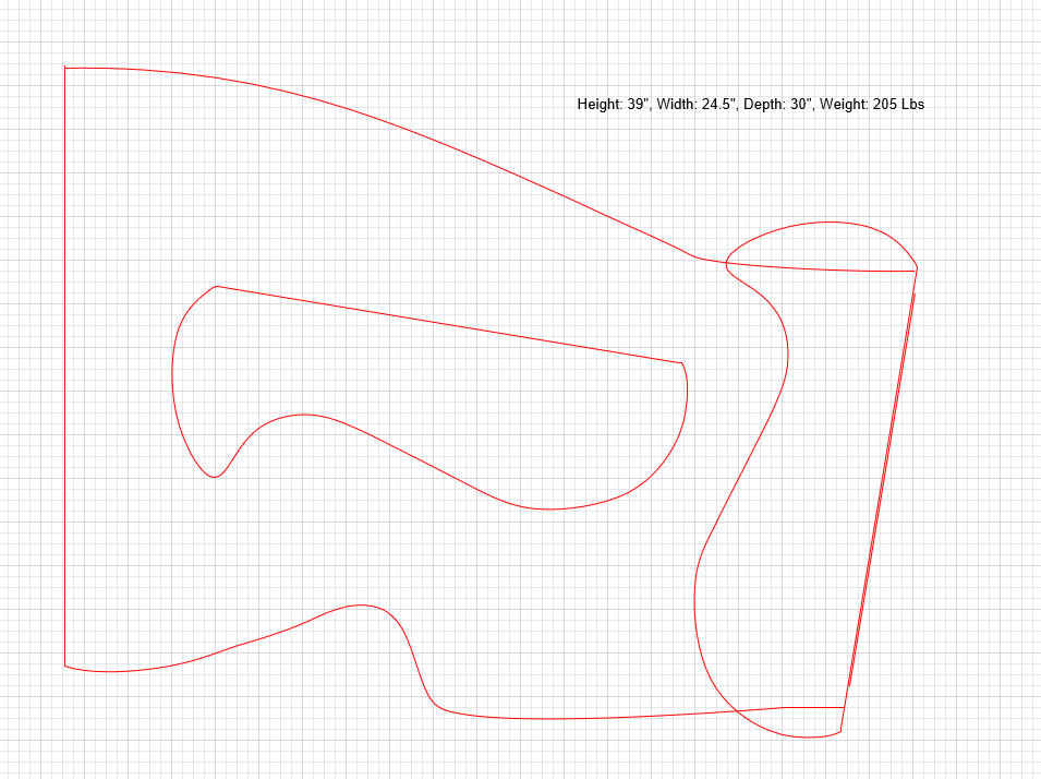
While simple, this was exceptionally helpful - it allowed me to get the general shape and sizing for the unit. My preferred 3D design tool of choice for years has been SketchUp. There used to be a truly free version back when they were owned by Google, but now they provide a "web" version for free, which isn't the ideal venue for real design work.
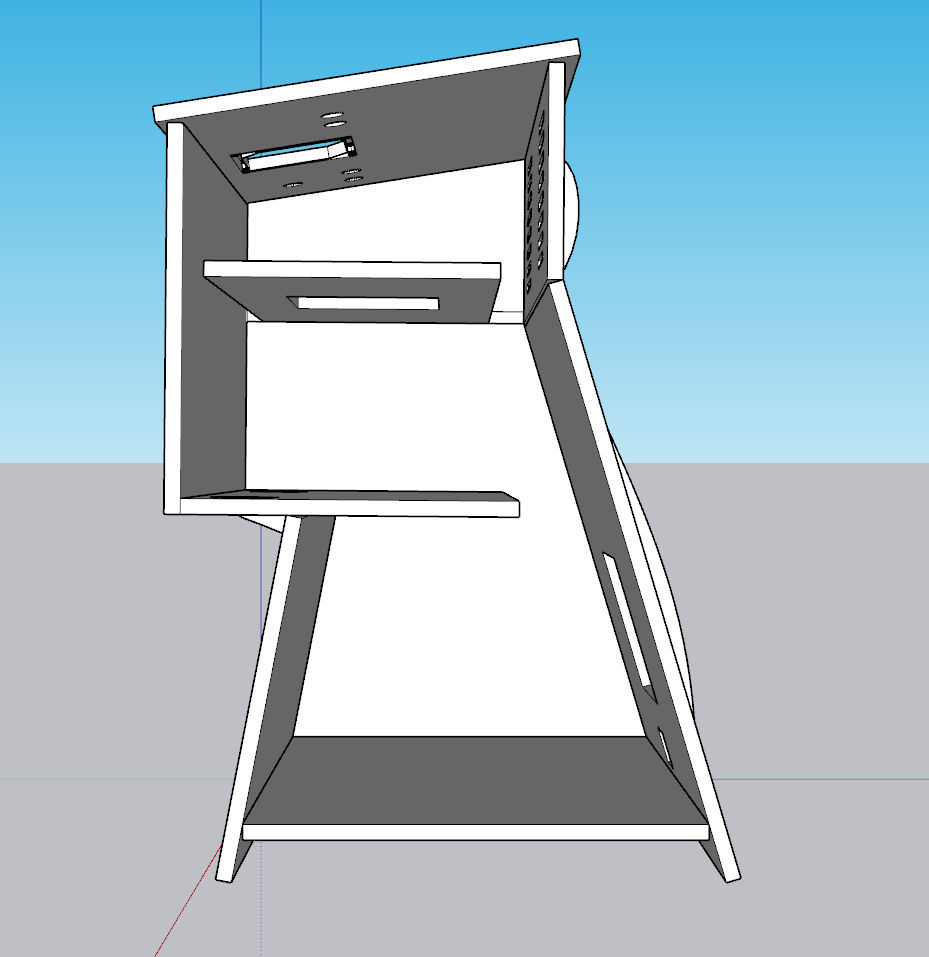
Fast forward a few weeks and here's where I landed:
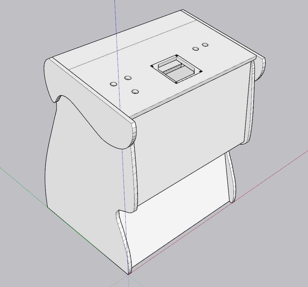
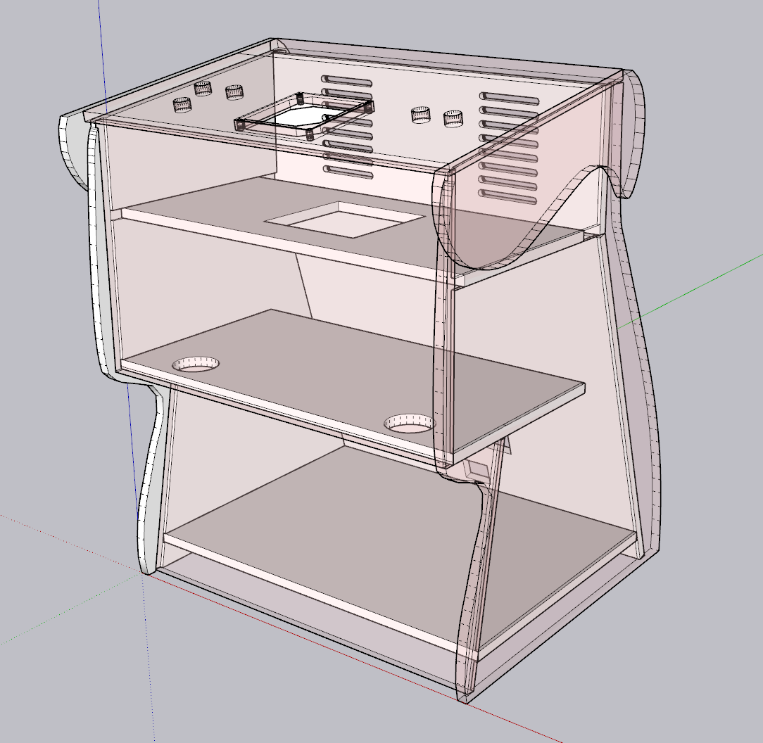
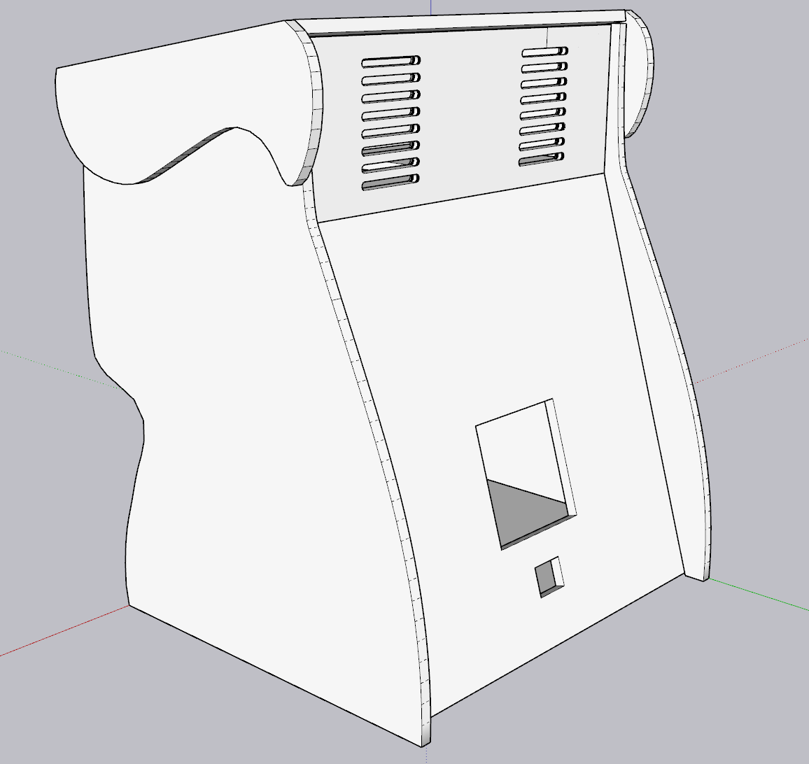
My Golden Tee "Fore" Showpiece cabinet design in SketchUp
Some of the challenges I pondered with this design:
- Unit width
- Speaker placement
- Access once assembled
- Stability/weight
- Airflow
- Control panel design and access
I'll review each of these, though note that there are many dependencies between them and these aren't necessarily in order.
Unit Width
Although the previous design linked above called for a 24.5" width, I knew I needed the unit to be wide enough to support the original control panel. My research showed that the control panel is 31 1/8" wide. So simple enough, the control panel would be 31 1/8", but then each of the "inside" support pieces would only be 30 1/8". This difference of an inch is explained by:
- I have to subtract out the thickness of the sides themselves. I decided early on in the project that 3/4" MDF was going to be the wood and thickness of choice, so allowing the control panel to rest flush on top of the side panels would require I subtract out 0.75" x 2 = 1.5"
- To get down to 1", I then had to re-add in 0.25" channel that was created in the sides (to allow each piece to fit perfectly). Given this 0.25" was inset into the side, the math effectively became (0.75" - 0.25") x 2 = 1"
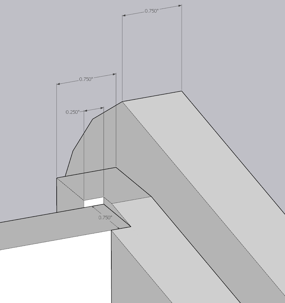
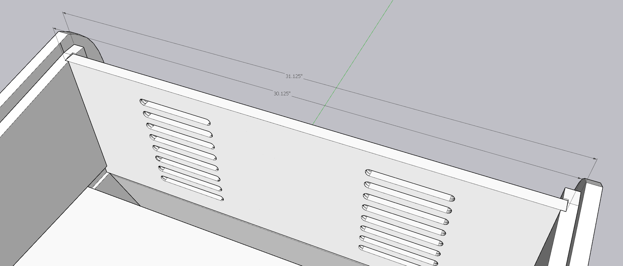
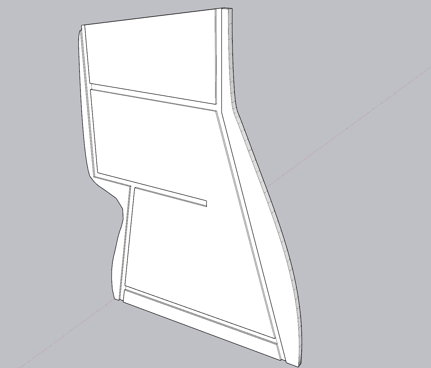
These two views help articulate the width considerations explained above.
Speaker Placement
In the original tall cabinet version of the same, the speakers are mounted above the monitor and thus fire down. Not having that luxury, I was relegated to either placing the speakers on top of the unit, directly on the control panel, downward firing, or totally internal. I did some virtual test fits on the top and found that if I wanted to use a 3" speaker, I would overshoot the back of the unit. Not to mention, speakers have depth to them, so I would have to somehow extend my back panel to "fit" the speakers.
Not ideal, so I shifted gears to using a downward firing approach. I figure no one plays a 15 year old game for its stellar audio, so all I needed to do was allow a speaker to be loud enough. Given the audio was downward facing and would likely reverb off the ground, I could create a small spatial audio effect.
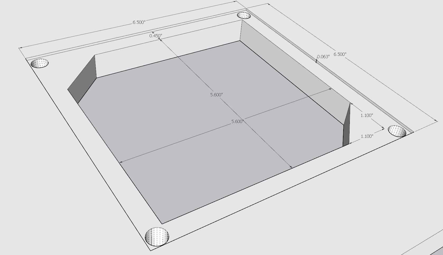
You can see in the below images that the "shelf" extends a little under 6", the last 0.75" of that comes from the width of top panel (which I've shown in a translucent pink). The extra 0.01" is a shortcoming of an imperfect design.
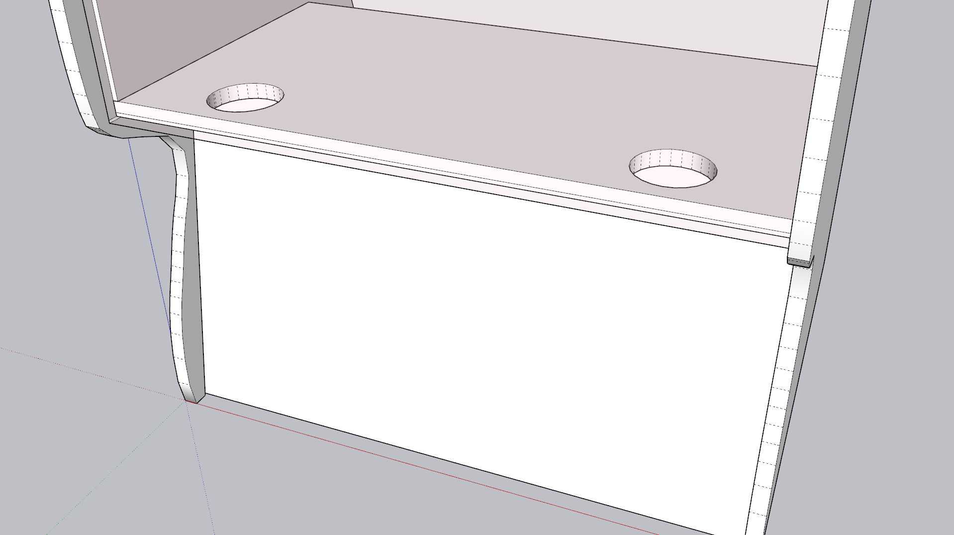
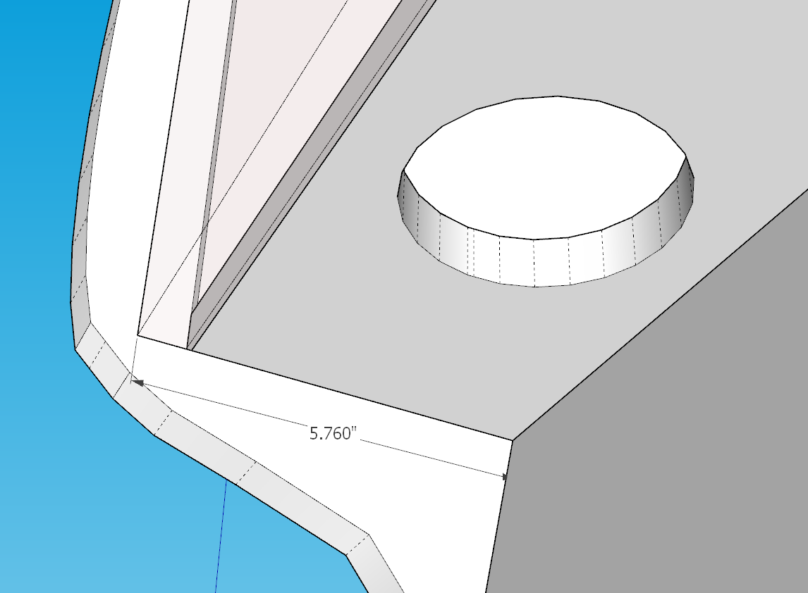
You can see the "shelf" I used to mount the speakers.
Access Once Assembled
I knew it would probably be smart to design the unit such that I could access every interior part if need be. Given my "shelf" based design, I did a few things:
- The top shelf purposefully had gaps left on the front and back (if you were facing the unit from the front). I envisioned this mostly for wires.
- That same top shelf has a large, 8" x 8" opening cut in the middle of it. I figured this was the largest size I could go without threatening the structural integrity of that panel. This would allow me to "reach" below to the second shelf if needed.
- The lowest shelf would only be accessible from the back of the unit. Borrowing from the actual Golden Tee Showpiece design, I added another 8" x 8" opening, this time to add a small door allowing access to cabling and the like.
- I included one final hole under the access door that I intended to put a wire passthrough. I knew I'd need to run both power and an HDMI cable out of the device, so this was an easy way to design for that without relying on a cable just randomly coming out of a hole in the unit.
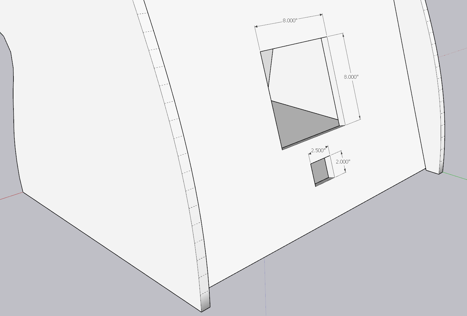
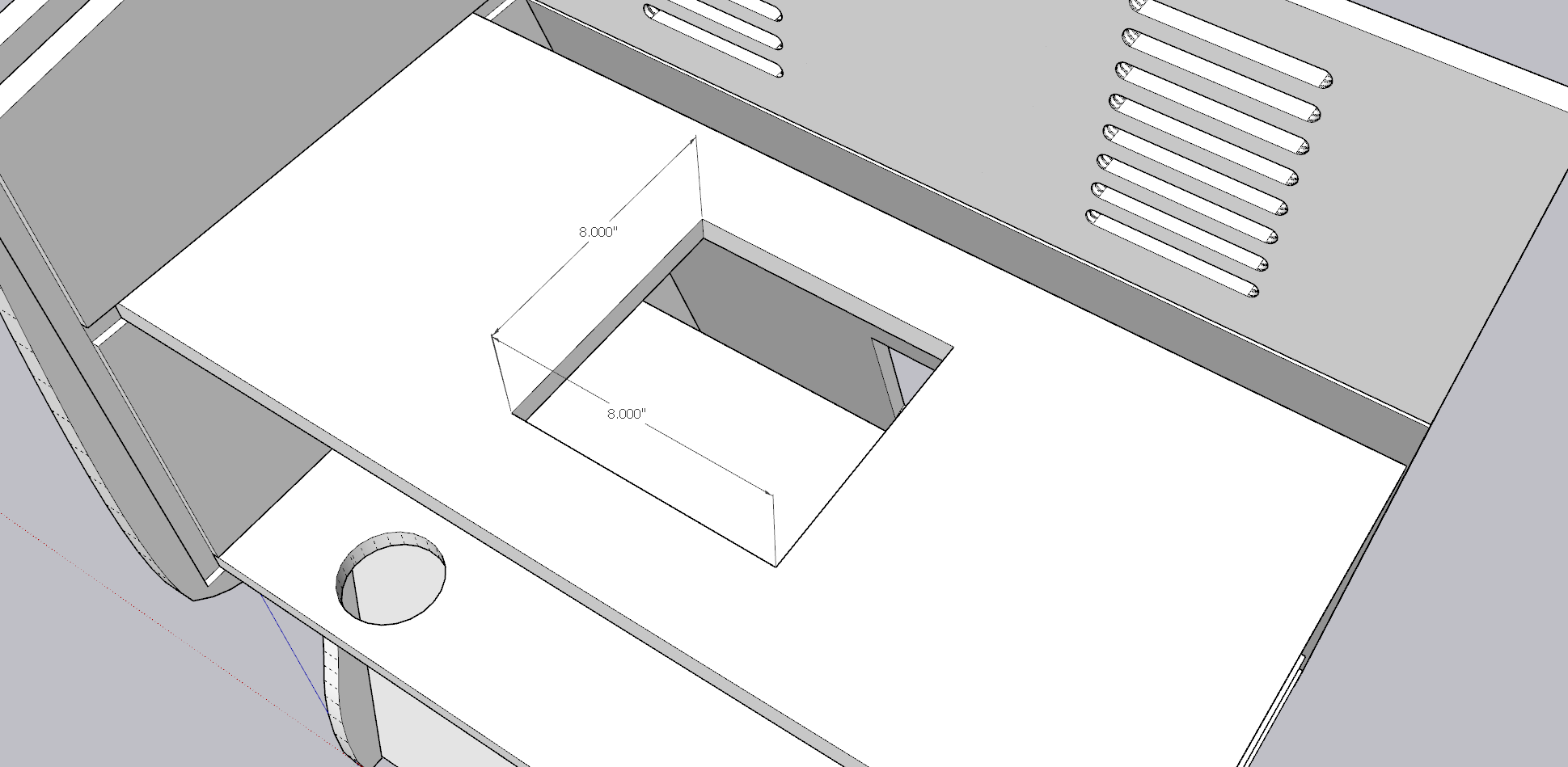
Views of the openings designed into the cabinet.
Stability/ Weight
This seems like a simple topic, but I knew I was designing a cabinet that guests may often lean into, smack a trackball, or otherwise apply pressure to it unlike most furniture.
To solve for stability, I made a conscious design to design a 0.25" channel into the main sides. This mean that I could take the machined wood and effectively "slot" it right into these channels. I would of course still screw it together, but this would provide an additional level of security, removing much of potential to "torque" the unit by forcing each piece into a clean right angle.
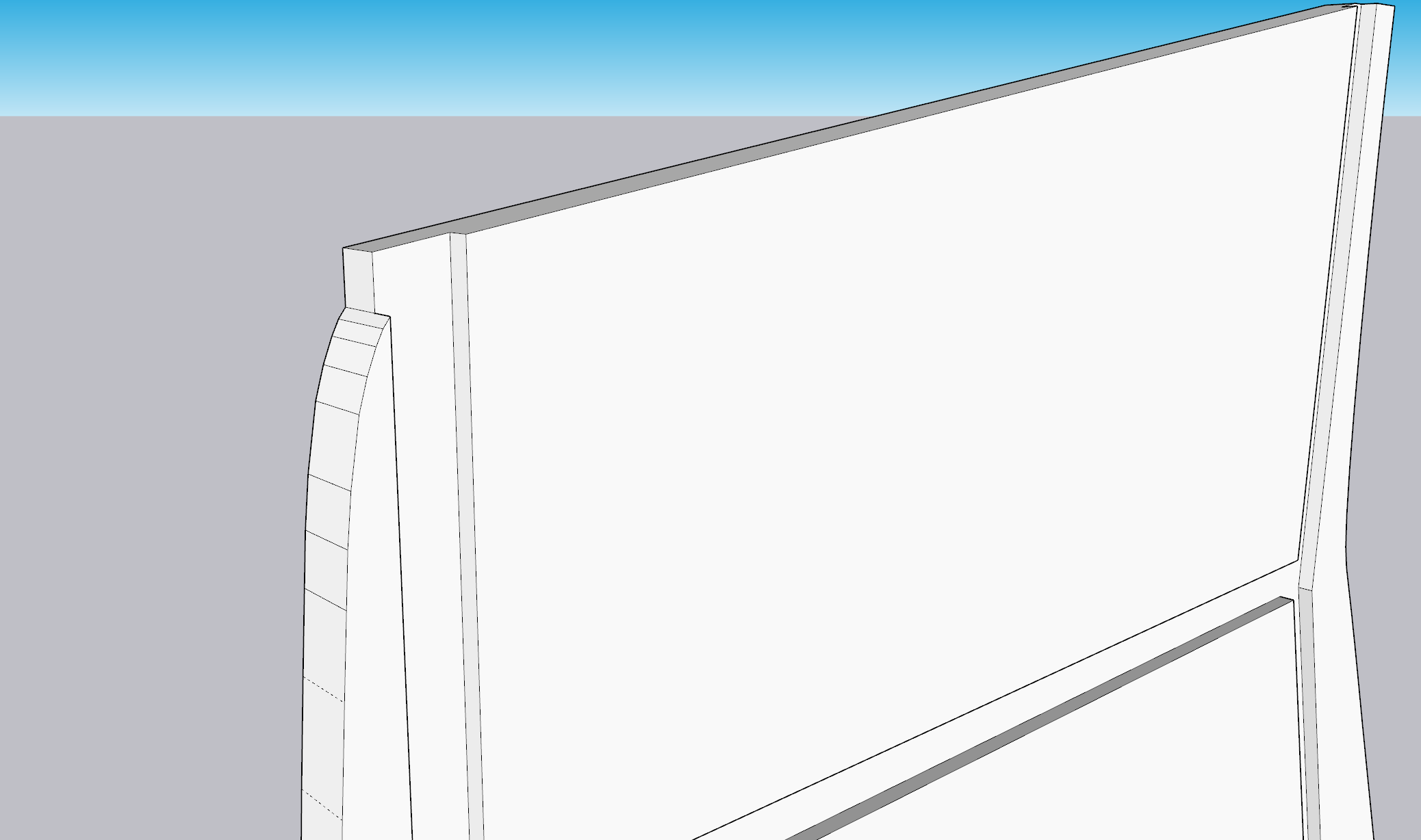
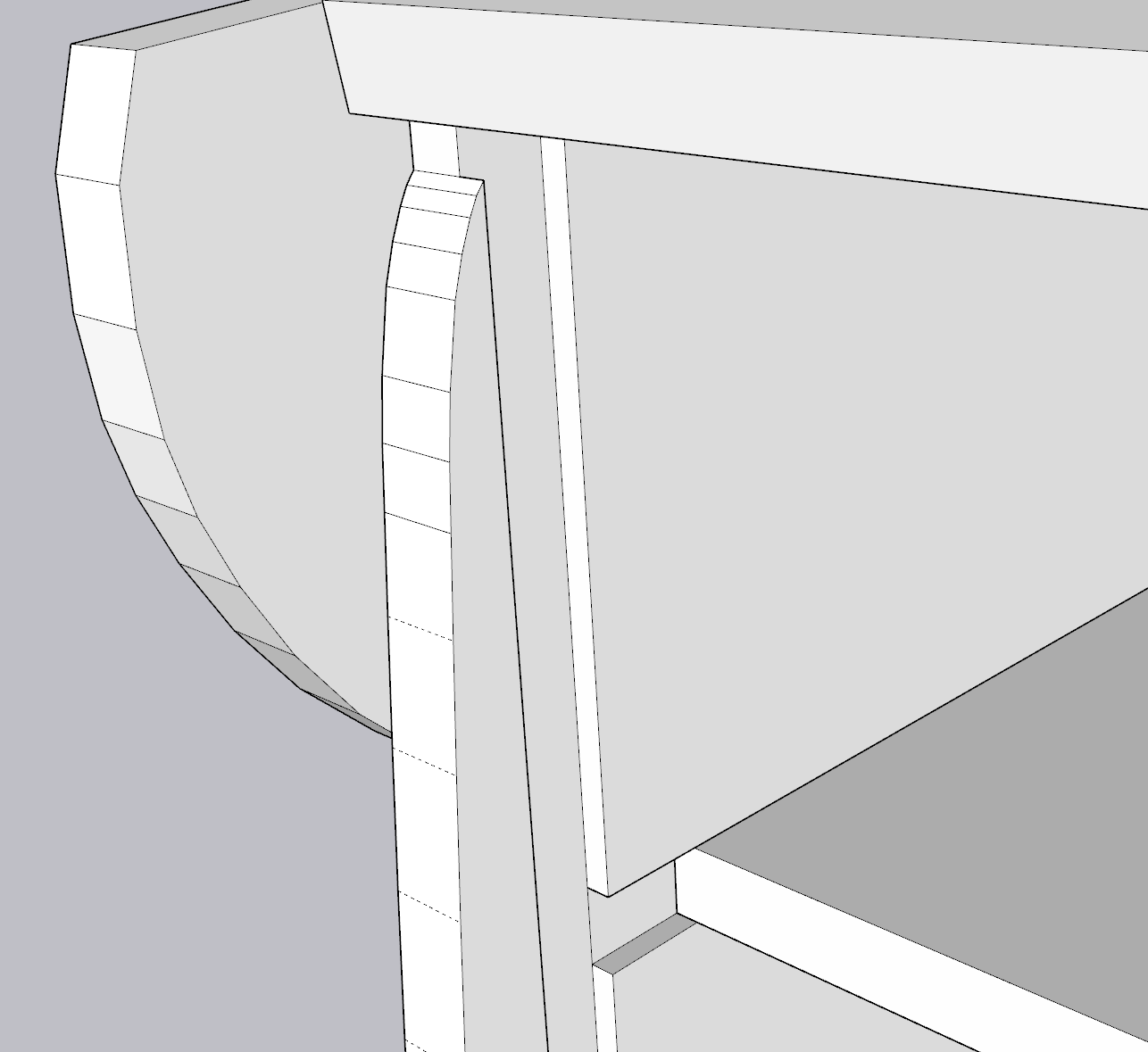
These views show a few closeups of the "channel" system that was designed.
The middle shelf likely didn't need to be as long is it, but I felt adding more stability here wouldn't be a bad thing. Not to mention, it helped contribute to the weight of the unit.
Per the weight, I'm using the baseline estimate of MDF weighing approximately 50lbs per cubic foot. If I loosely sum each piece of the unit, I end up with about 54 square feet, using 3/4" MDF sums to about 3.375 cubic feet. Doing the math, I estimate just the wood alone would weigh 169lbs. Subtract a little for the portions that are cutout. In hindsight, I probably could have gotten away with 1/2" MDF, but things just feel much more study with the 3/4".
Airflow
I skimped a little on this one, based on what I knew from the existing Golden Tee Showpiece, it seems that leaving openings for ventilation in the back of the unit was all that would be required.
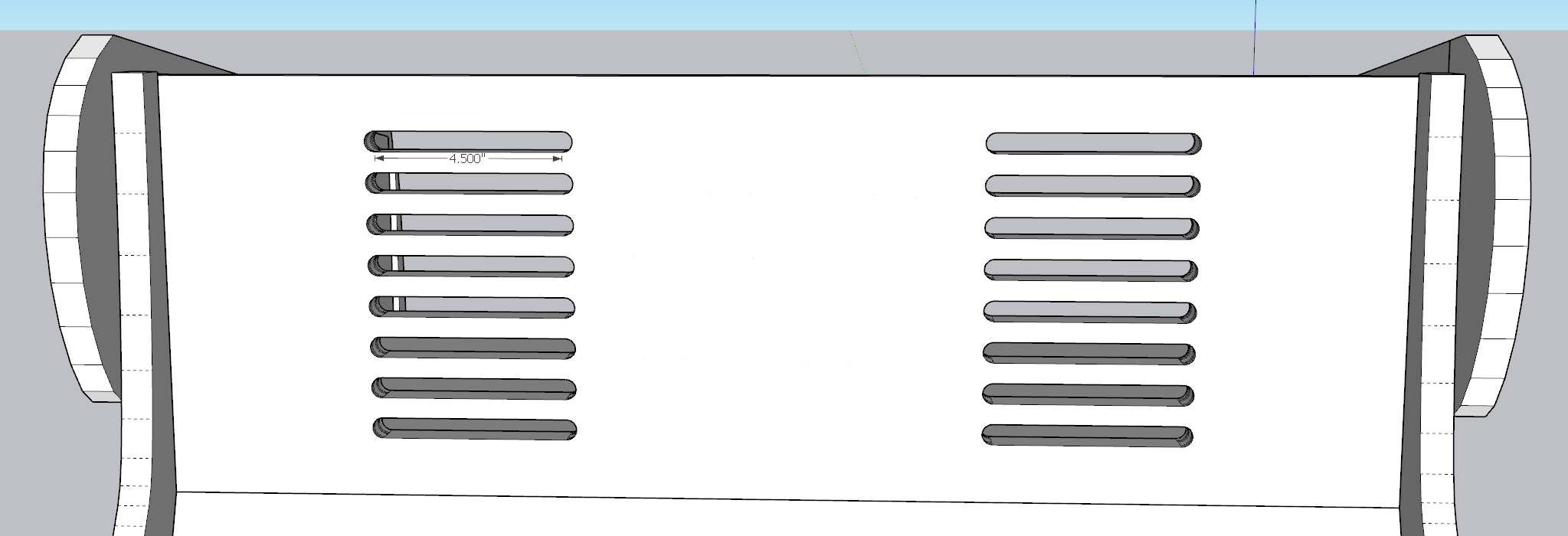
I created a series of half-inch thick, 5" wide ventilation holes. For placement, I started by splitting the back panel into two pieces (dividing down the middle), then doing that again with each half. It created this separation which felt appropriate.
Control Panel Design and Access
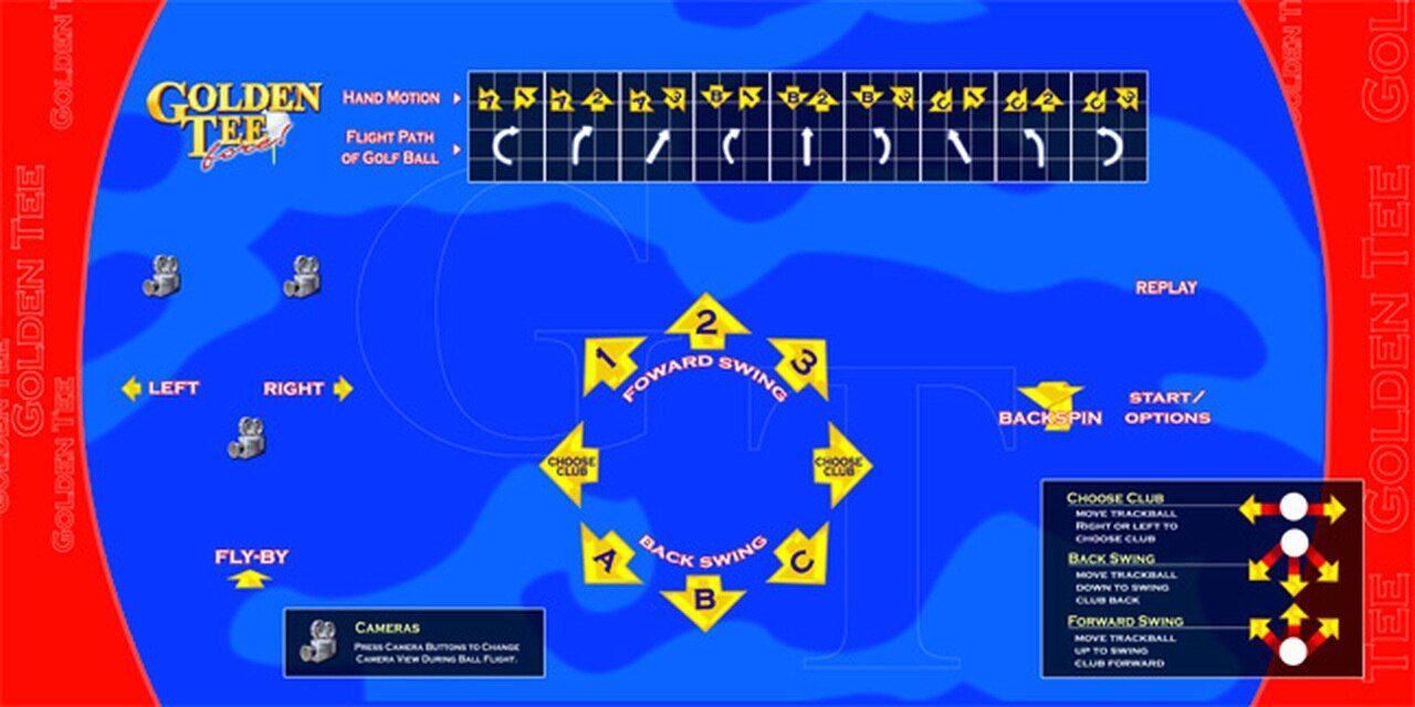
I struggled with the control panel for awhile. I knew I would need to acquire or print the actual control panel overlay, so I was stuck having to approximate the design, as well as the placement of the holes for the buttons and trackball.
There's only a handful of choices out there for overlays, but I landed on the services of ArcadeOverlays, specifically for GT Fore. Although I think $50 + $10 shipping is overpriced for what is effectively a poster print, I will give them the benefit of the doubt in terms of how they either acquired or well recreated the control panel design.
The primary challenges I faced was the image provided on their website did not appear to have the button holes centered:
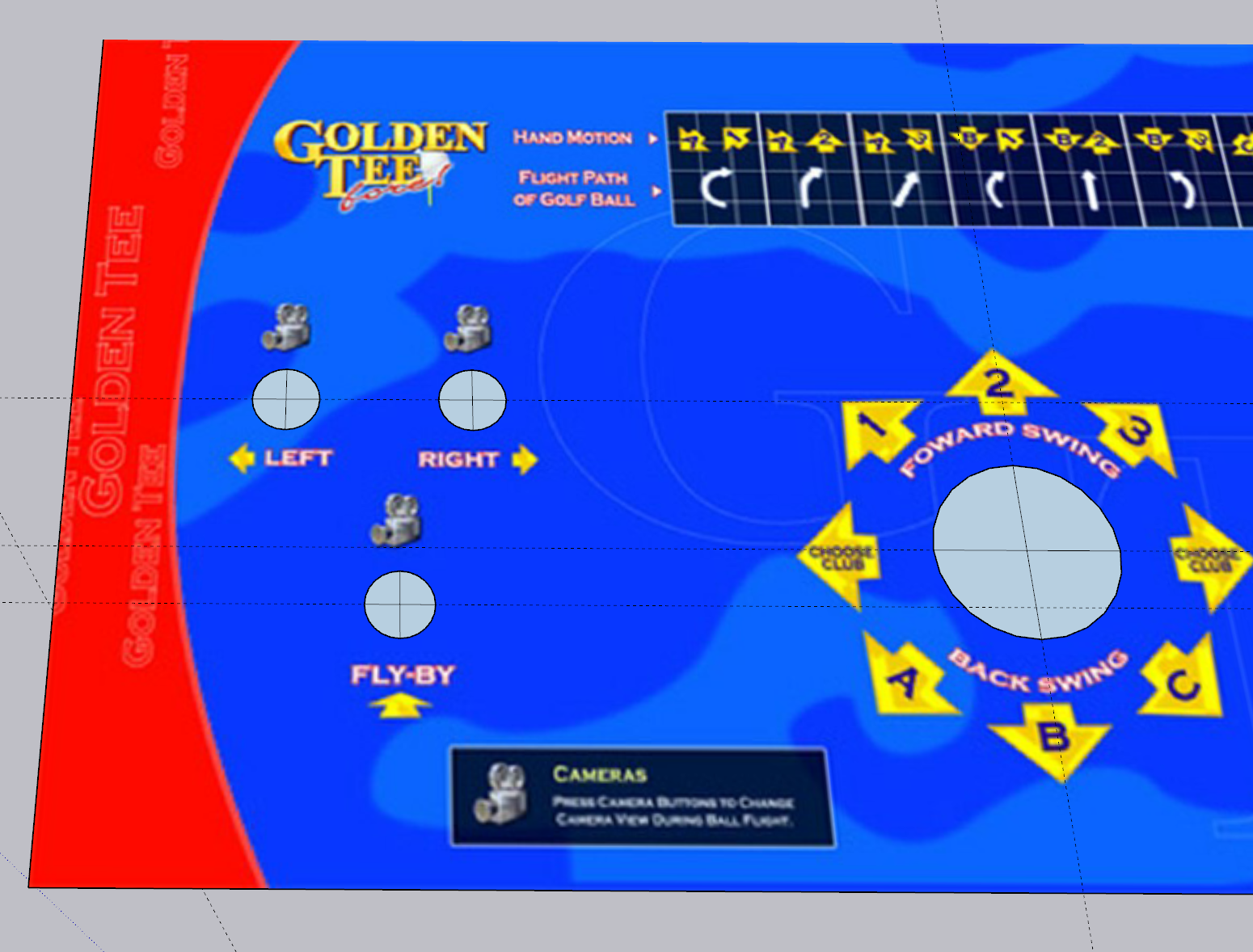
I ended up emailing them and was told that the "source" file they use had the buttons correctly centered, so the preview image at some point must have been incorrectly updated/ uploaded. They did offer me a PDF of the overlay for an extra $20, but given I wasn't in the business of recreating this long term, I resulted to just guessing since I needed to get my design above sent off to the shop to be milled.
One other challenge was how would the trackball mount? This is notably dependent on the trackball you purchase, but wanting to stay true to original game, I tracked down the original trackball: Suzo Happ 3" White Trackball
Thinking ahead, I purchased the version that includes a USB/PS2 output directly, rather than having to rely on wiring the device up to some encoder. Also worth noting - I did not buy straight from Suzo Happ; you can find these trackballs pretty readily and for much cheaper on eBay and other sources. I think I sent just under $100.
You'll also want to pick up a mounting plate. The idea being that if you create a pocket on top of the control panel, you can then bolt the trackball into the mount plate from the bottom of the control panel. This prevents you from needing to have exposed screws on top of your control panel. Same eBay logic is true here as well.
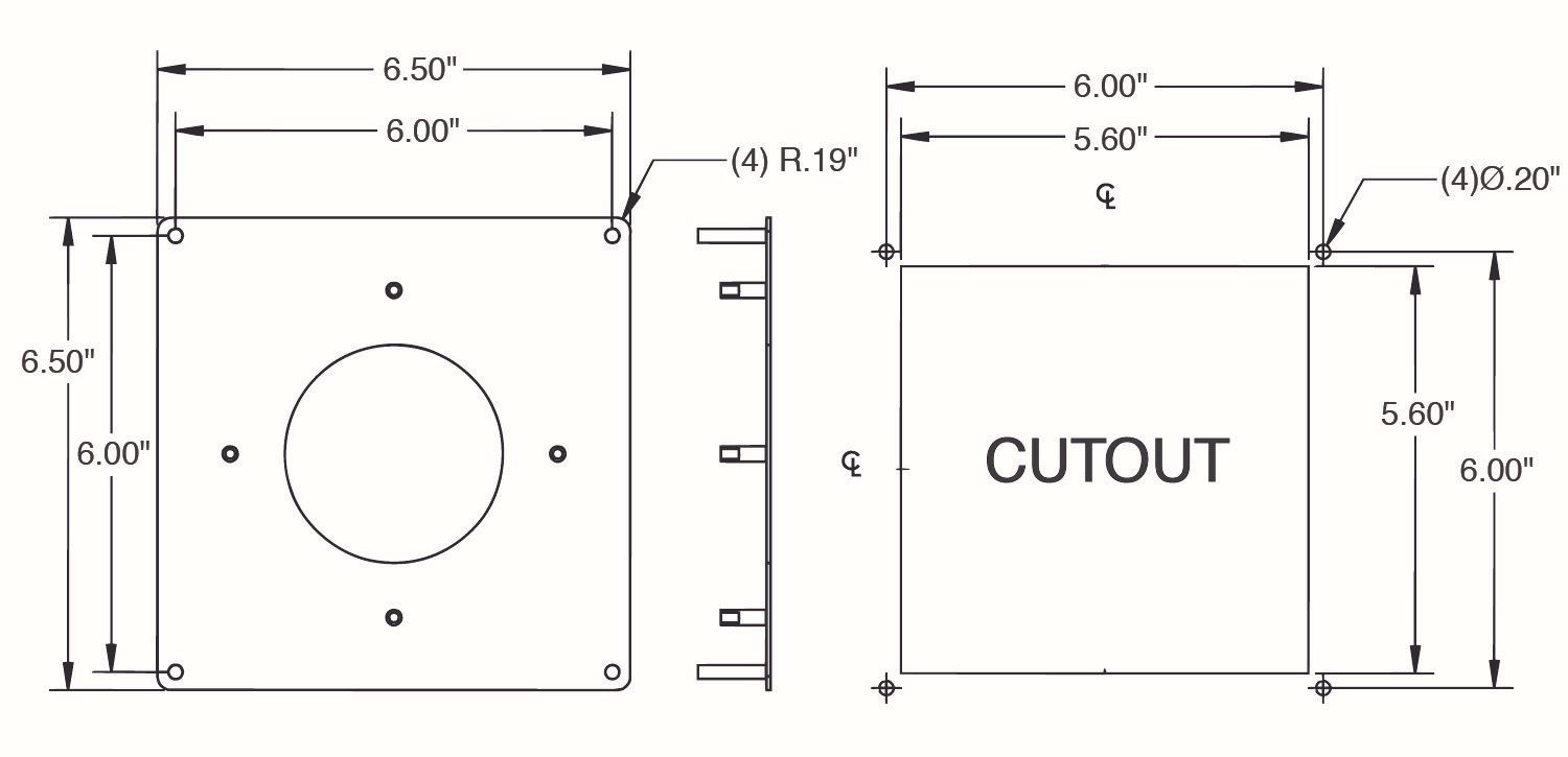
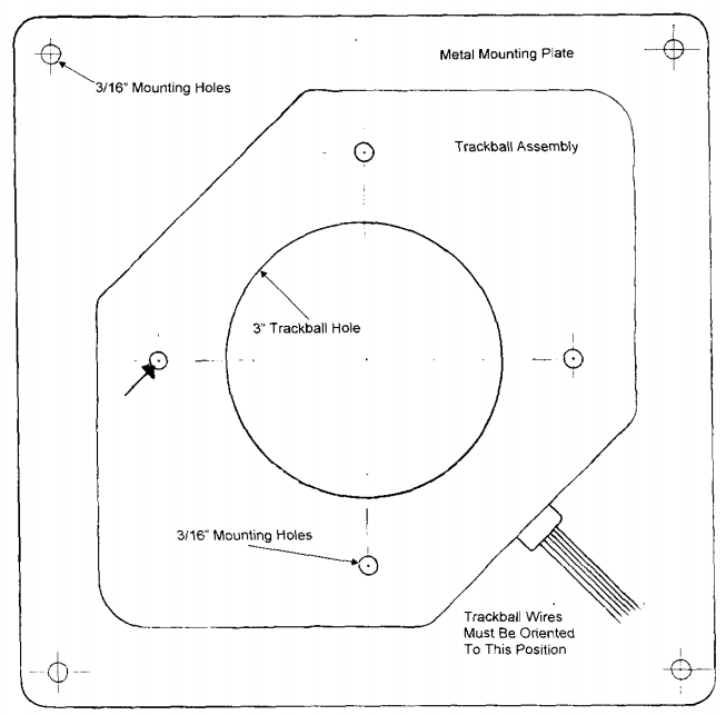
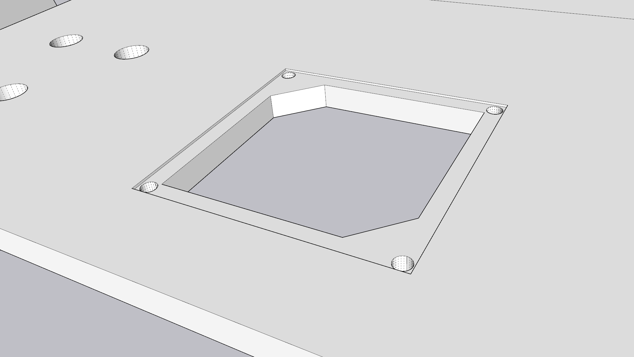
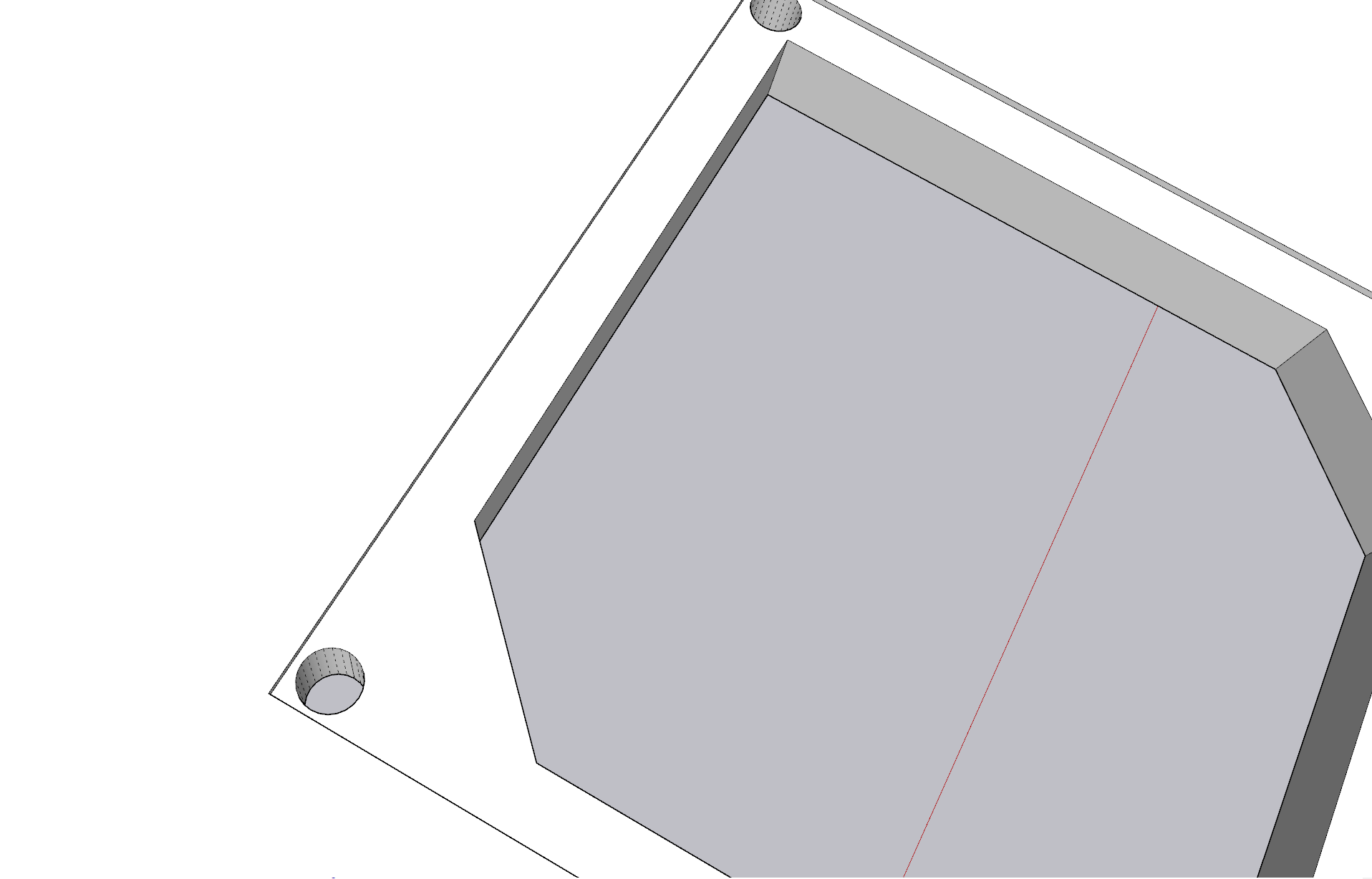
Close-up views of trackball mounting hole
In the above, you can see how I based all of my dimensions off of what I was able to piece together from the documentation of the mounting plate, as well as old Golden Tee documentation.
I opted to add the little "ridges" on the top left and bottom right for two reasons:
- I knew the shape of the trackball itself would leave an opening for these so it would "force" the orientation to be correct.
- It would add more surface area for the metal mounting plate to rest on, hopefully increasing the stability of the trackball even further.
Real quick - the buttons themselves are also Suzo Happ brand as well. You can pick them up for a few bucks a piece from a host of online retailers.
Each mounting whole I designed as 1.125". The provided spec rounded it up to 1.13, but I didn't have a problem with 1.125" and the buttons ended up being a perfect fit. To stay true to the game you'll need 4 white buttons and 1 red for the "start" button.
Tie it together
One weakness of Sketchup is that it isn't quite a vector tool that often creates unexpected results. Something as simple as angles being off by fractions of a degree can have bad results. Although the "proper" tool would been a pure vector tool like CorelDRAW, I wanted to stick with something familiar. I ended up extracting each "face" of the design into a "flattened" file.
Design Caveats
Consistent with the "weakness" of Sketchup, you can see a number of non-standard dimensions above. Some of this is inherent with the "fluid" nature of the design; I wouldn't expect some of the curves to line-up perfectly, and many of the panels have non-standard heights as an effect of needing to fit into the channels.
One pro-tip I learned after awhile: the easiest way to convert a 3D shape into a 2D one is to simply scale it, reducing the Z axis to zero, such that it "removes" all elements of height. Sadly, Sketchup's native scale tool doesn't support setting an axis to zero... but I found a plugin that does! Much credit to FredoScale. In my case, I was able to compress each piece into a 2D plot. Here's an illustrative example:
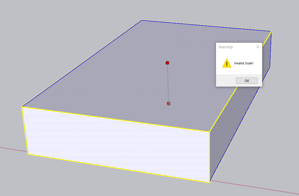
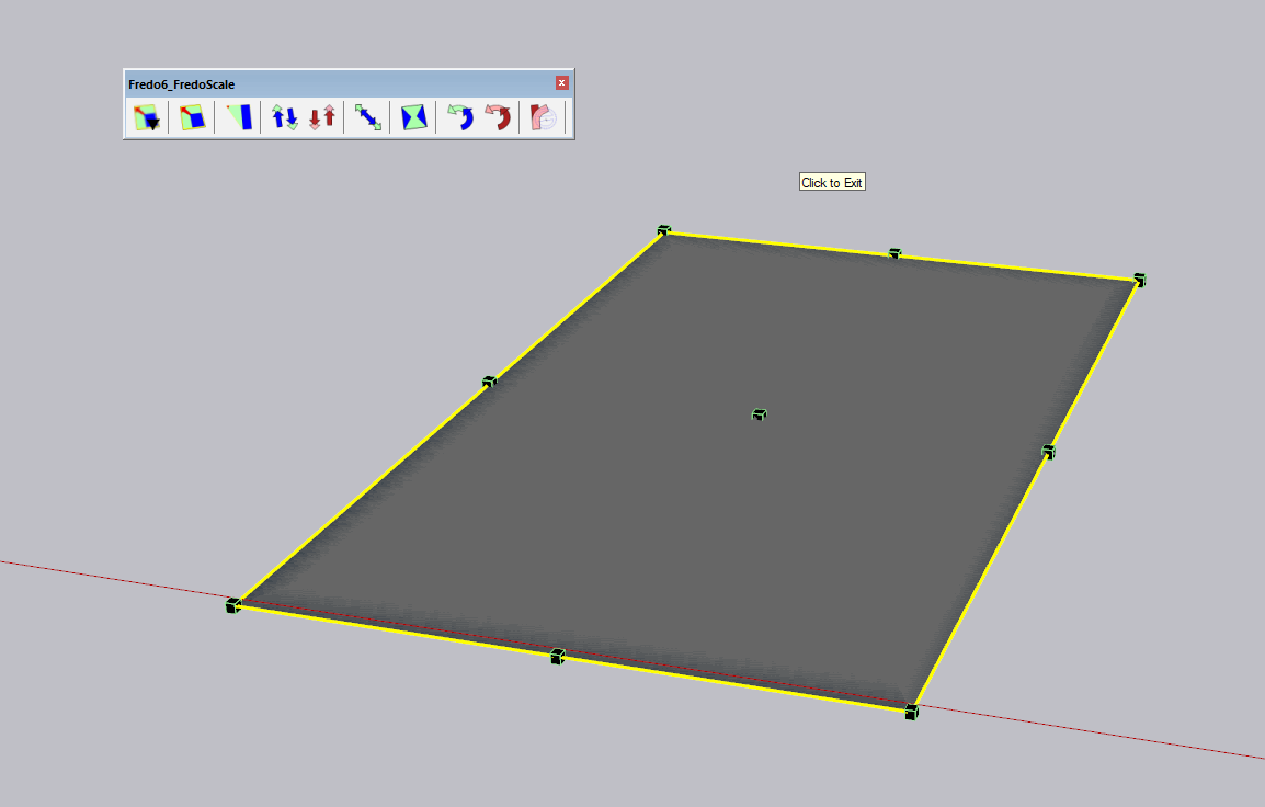
Left: default Sketchup scaling limitation. Right: FredoScale Box Scaling.
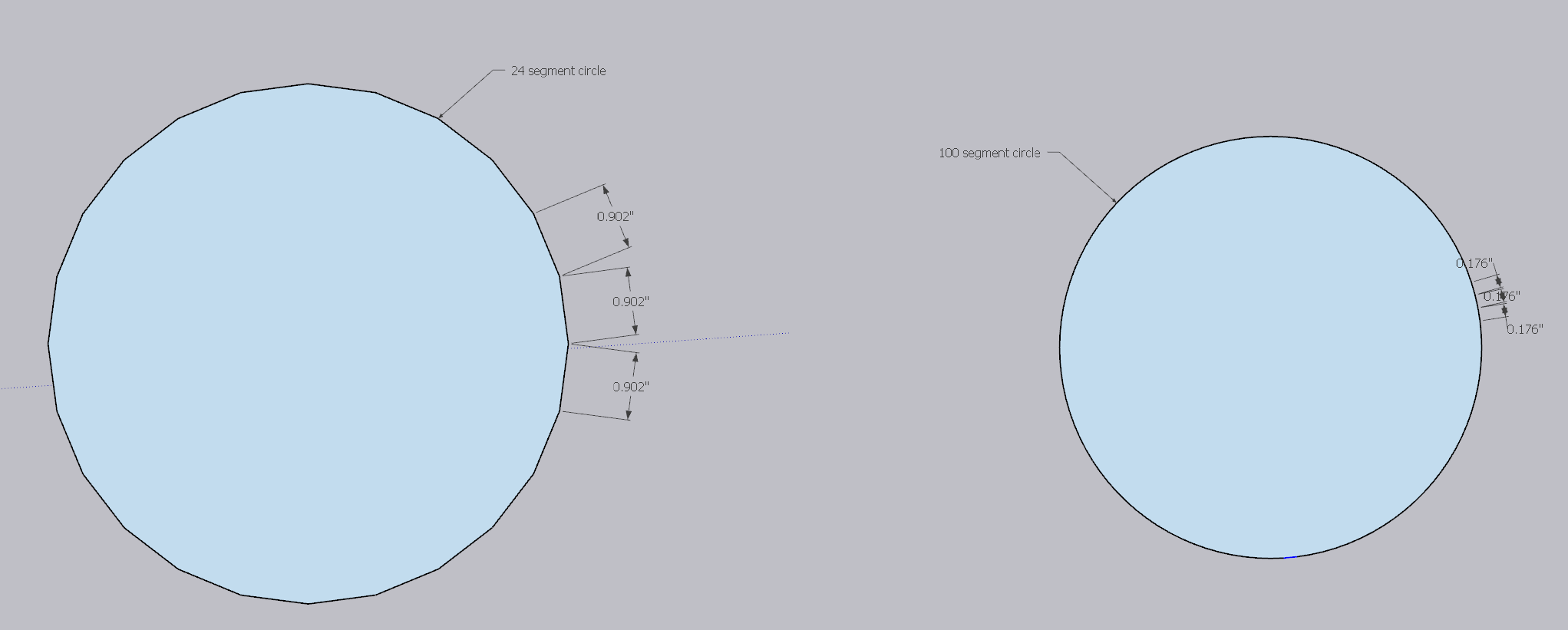
You also need to be careful when dealing with "smooth" lines in Sketchup. I'm not sure if this limitation exists in other software, but effectively whenever you draw a smooth shape like a circle in Sketchup, it creates it from a series of straight lines. For circles, that default is 24, which means for a big enough circle, you may end up with noticeable edges. The fix is simply to bump the number of "segments" in a circle to a much higher number. I used 100 and didn't have issues.
Lastly, this also applies to how you draw smooth lines like some of the curves that appear on the sides of the unit. When converting my 3D design into a 2D CAD file, I noted my "curves" were no longer smooth.
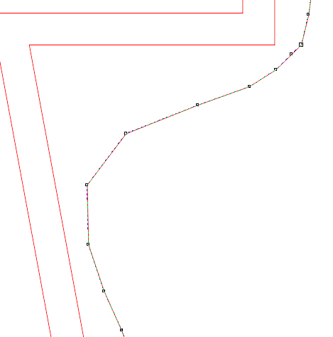
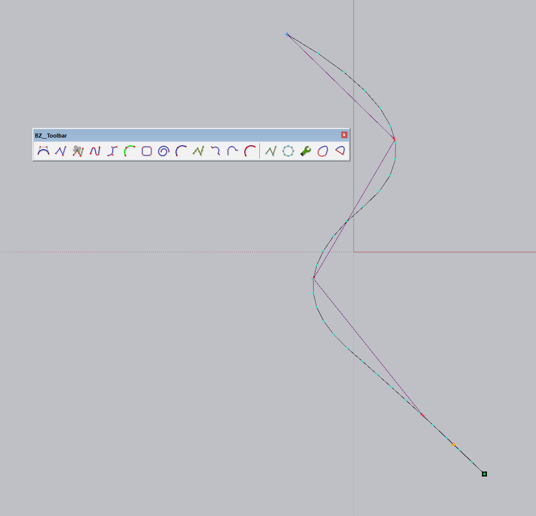
Luckily, Fredo came in handy again with their Bezier Spline plugin. Although it looks like there are tons of options to build a line up manually, I ended up using a "convert" function to map my old lines into smooth ones. Here's an example line I crudely drew to visualize, though the same concept holds true for each smooth curve on the unit.
Send off to mill
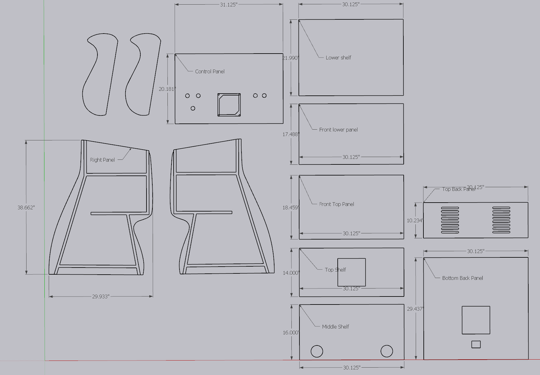
The last step was to package up the CAD file and send it to my local CNC shop. Their CNC techs mapped the cutting path into a workable shape, handling all of the tooling considerations, and laid about all pieces across two 4' x 8' sheets of 3/4" MDF.
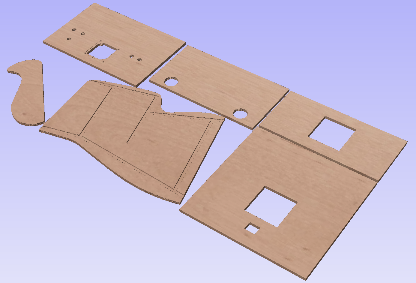
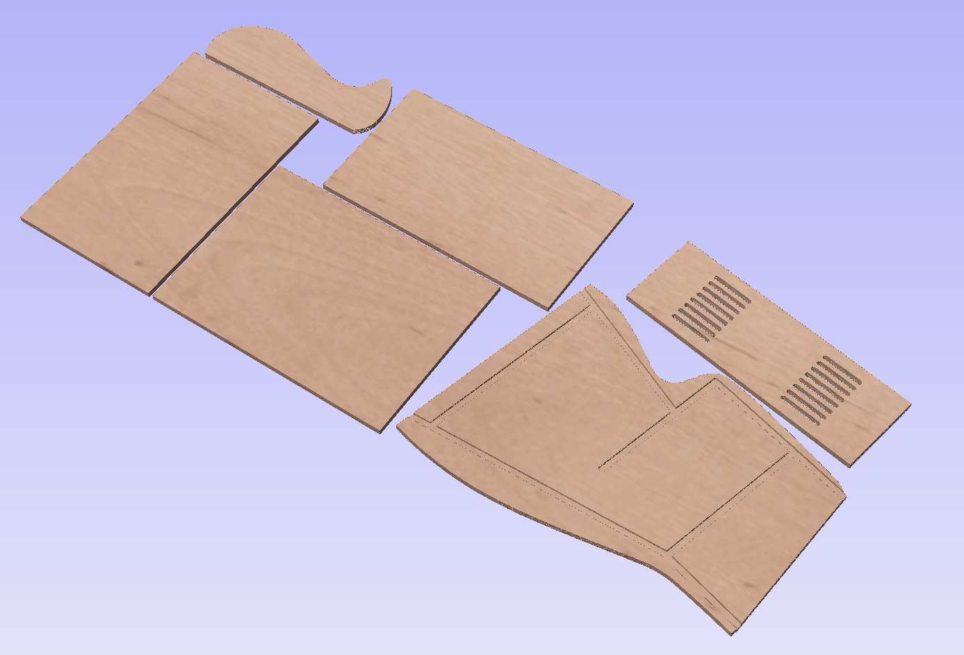
Preview of milled pieces aligned to a 4' x 8' MDF panels.
If you're curious, it cost just a bit over $230 to mill this at a local shop. They ended up having to redo it because they accidentally milled the first set in 1/2" MDF vs. 3/4". The only reason I didn't keep it is because the channels and alignment of pieces, particularly on the top, were done specifically expecting 3/4" MDF.
When they redid the job, it took less than an hour total, yet I was billed for 90 minutes. I wasn't in a place to complain as I'm not a regular and the team had already gone out of their way to re-mill my parts late into the night. Here's the breakdown if interested:
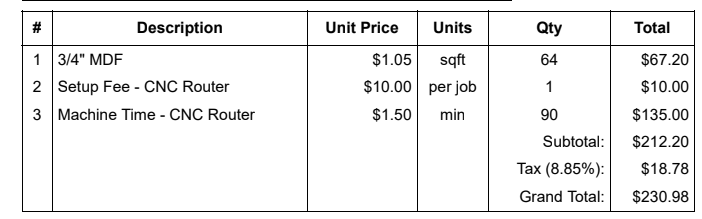
If I were a member, I would have saved the $10 setup fee, though I felt the price for MDF was super fair (particularly as this phase of the project was during a lumber shortage).
Build it yourself
If you made it this far, you're probably pretty interested in designing or building your own arcade cabinet. If you want to learn from my own trial-and-error on the project, jump start your own and get full copies of my 3D and 2D flattened designs, as well as a full build guide, plus even more pictures than I have here, consider supporting me:

Member discussion: